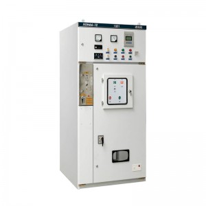
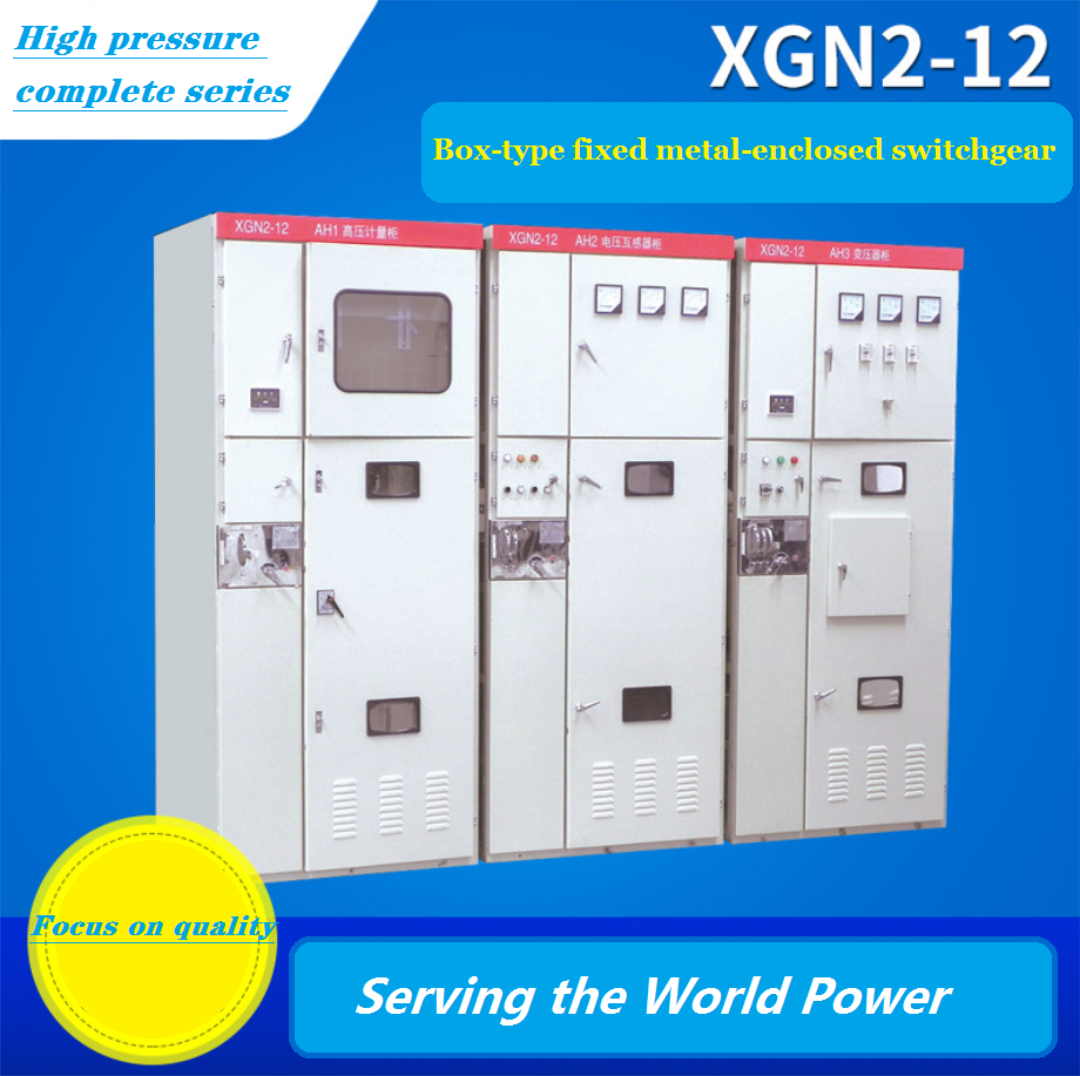
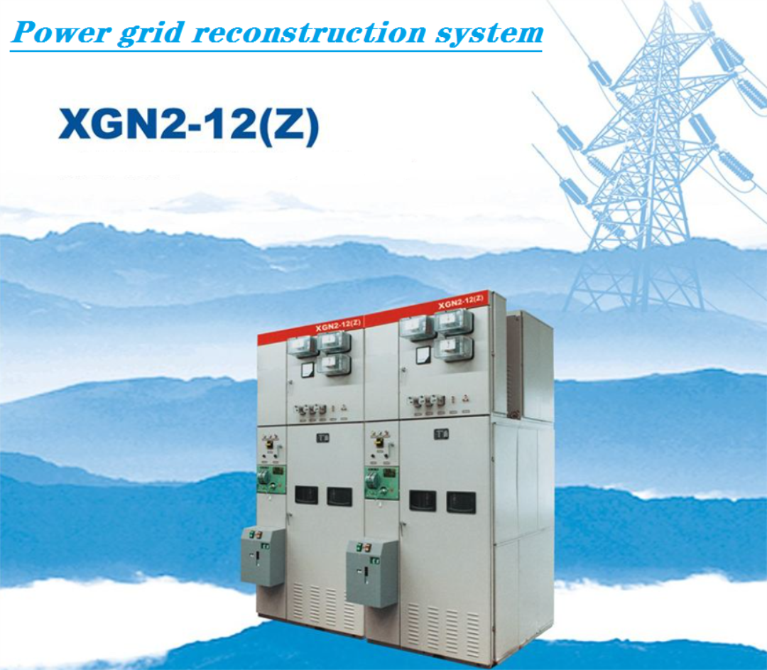
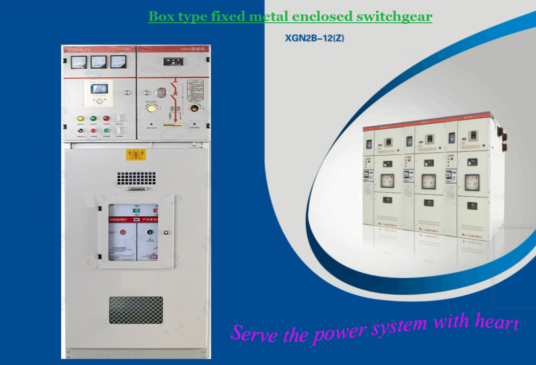
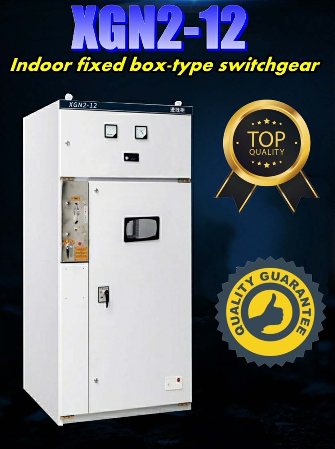
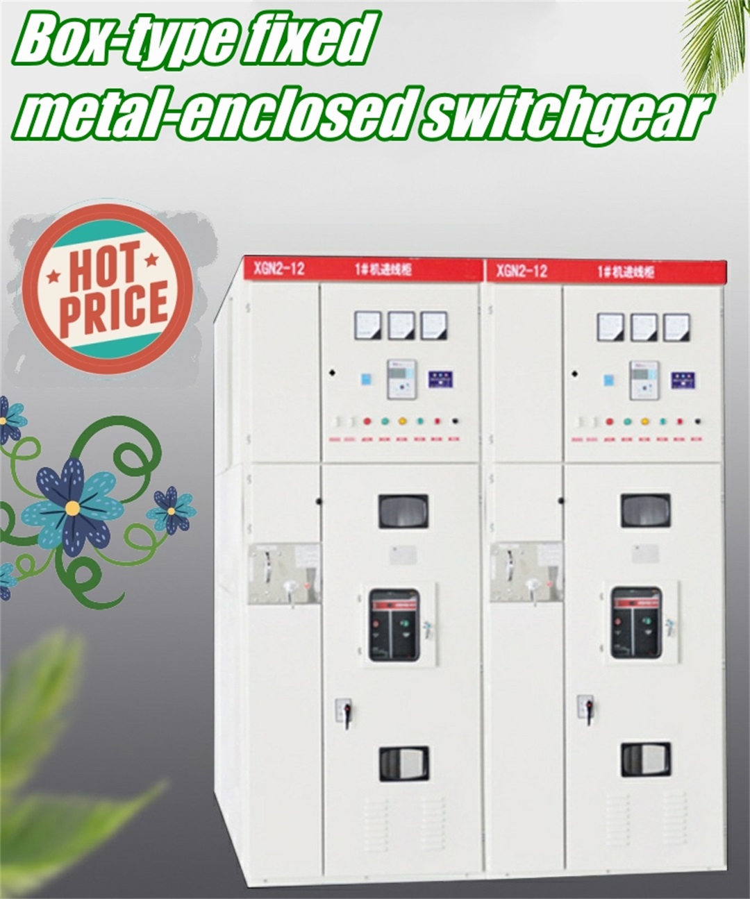
XGN2 3.6KV 7.2KV 12KV 630-2500A Indoor box-type fixed metal enclosed switchgear
Product Description
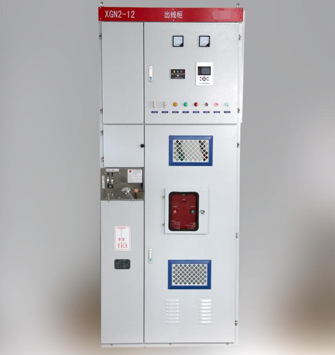
XGN2-12 box-type fixed metal-enclosed switchgear (referred to as switchgear) is used for receiving and distributing electric energy in 3.6, 7.2, 12kv three-phase AC 50Hz systems, suitable for frequent operation occasions, and its busbar system is a single busbar (and can be derived single bus with bypass and double bus structure). The switchgear meets the requirements of the national standard GB3906-91 (3-35kv AC metal-enclosed switchgear) and the national standard IEC298, and has two proposed "five-proof" locking functions.
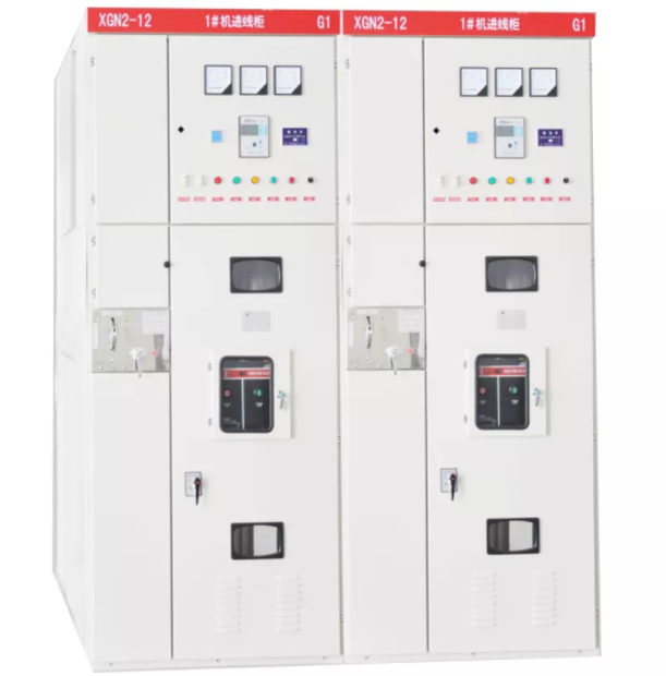
The main switch of the switch cabinet adopts ZN28-12 series vacuum circuit breaker, equipped with CDI7 series electromagnetic operating mechanism or CT19 series spring operating mechanism, and the isolating switch adopts GN30-12 rotary isolating switch or GN22-12 high current isolating switch series.
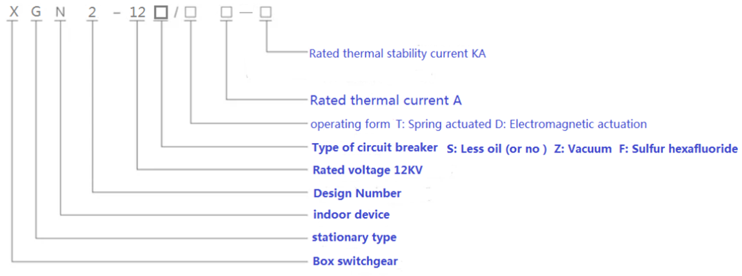
Model Description
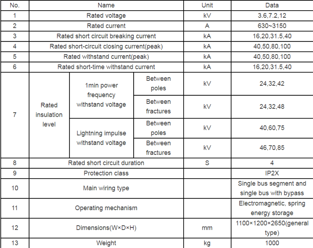
Product technical parameters and external dimensions
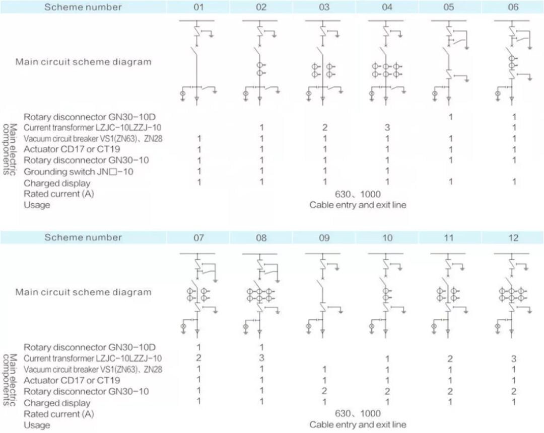
Main circuit scheme
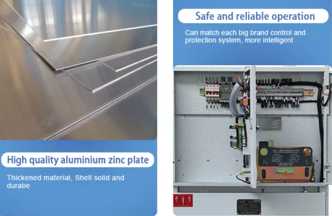
Product structure features
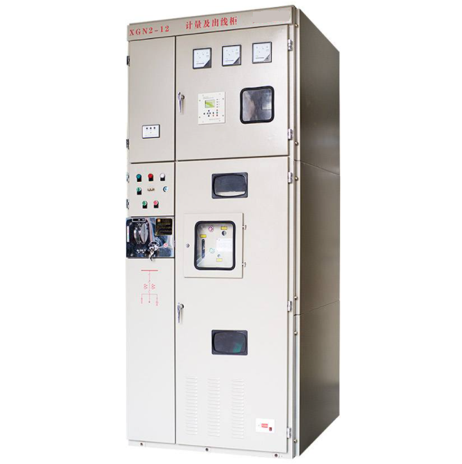
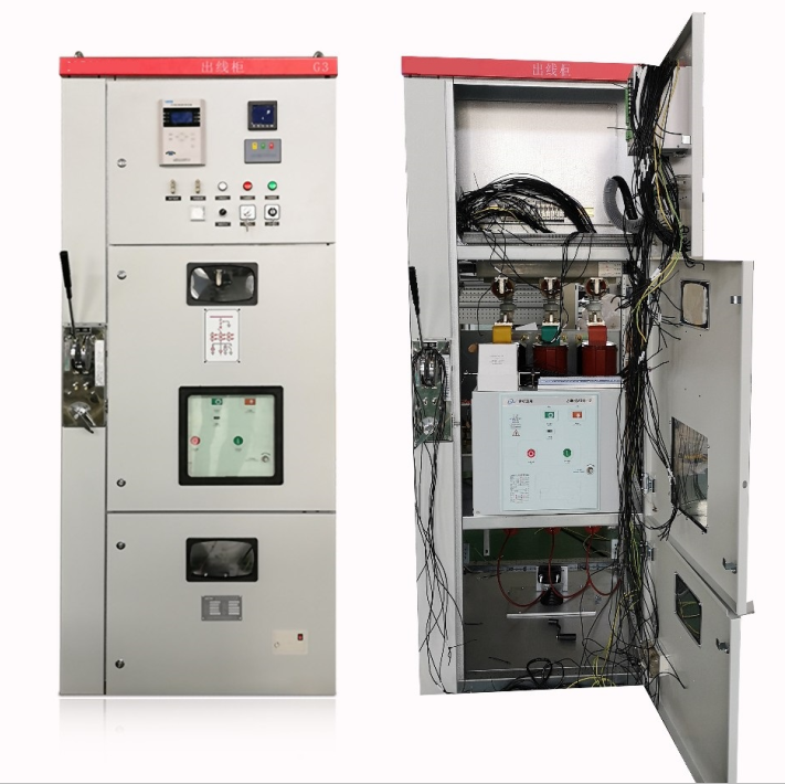
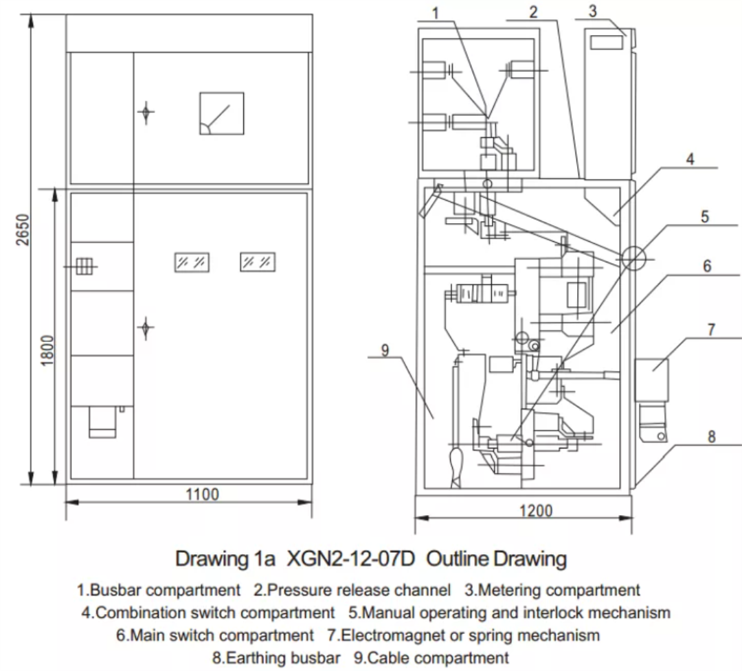
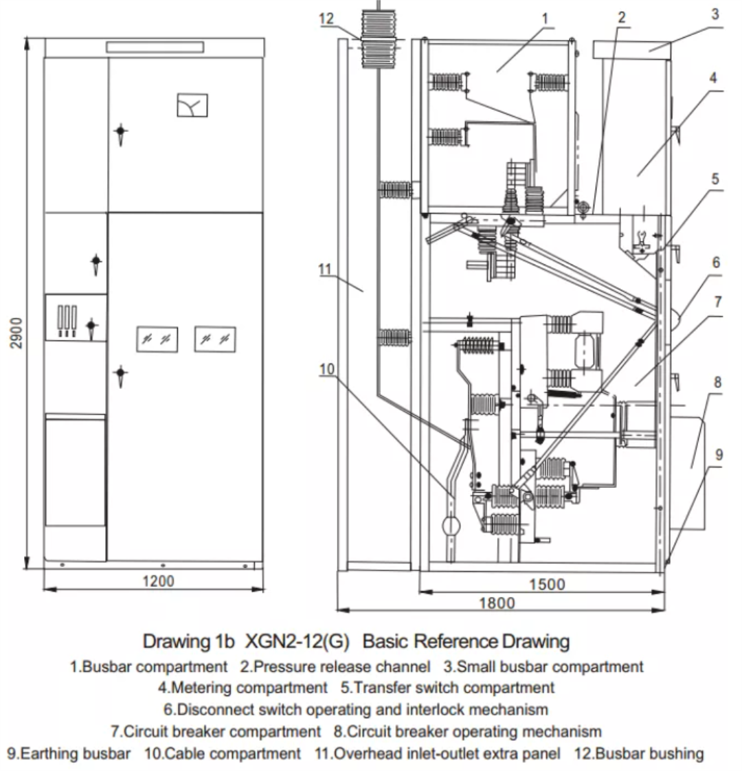
1: The switch cabinet is a metal closed box structure, and the cabinet frame is welded with angle steel. The cabinet is divided into circuit breaker room, bus room, cable room and relay room. The interior is separated by steel plates.
2: The circuit breaker room is located at the lower part of the cabinet, and the circuit breaker drive is connected by the pull rod and the operating mechanism; the lower end of the circuit breaker is connected to the current transformer, the current transformer is connected to the isolating switch terminal, and the upper end of the circuit breaker is connected to the isolating switch terminal. The circuit breaker room is also provided with a pressure relief channel. If arcing occurs inside, the gas can be released through the exhaust channel.
3: The busbar compartment is at the rear upper part of the cabinet. In order to reduce the height of the cabinet, The busbar arrangement shape is 品, it is supported by a porcelain insulator with a bending strength of 7350N, and the busbar is connected to the upper isolating switch terminal.
4: The cable compartment is behind the lower part of the cabinet. The support insulators in the cable compartment can be equipped with monitoring devices and the cables are fixed on the brackets. The contact is the wiring communication cable M of this room
5: The operating mechanism of the circuit breaker is installed at the lower left, above which is the operating interlocking mechanism of the isolating switch.
6: The switch cabinet is double-sided maintenance. In the front, the secondary components of the relay room are inspected, the operating mechanism, mechanical interlock and transmission parts are maintained, the circuit breaker is inspected, and the upper busbar and cable terminals are repaired in the rear. Lights are installed in the circuit breaker room and the cable room.
7:There is a grounding copper bar parallel to the width of the cabinet below the front, and its cross-section is 4*40mm². Mechanical interlock: prevent the on-load isolating switch; prevent the circuit breaker from accidentally opening and closing; prevent the grounding knife from closing.
Environment condition
1. Ambient air temperature: -5~+40 and the average temperature should not exceed +35 in 24h.
2. Install and use indoors. Altitude above sea level for operation site should not exceed 2000M.
3. Relative humidity should not exceed 50% at max temperature +40. Higher relative humidity is allowed at lower temperature. Ex. 90% at +20. But in view of the temperature change, it is possible that moderate dews will produce casually.
4. Installation gradient not exceed 5.
5. Install in the places without fierce vibration and shock and the sites insufficient to erode the electrical components.
6. Any specific requirement, consult with manufactory.
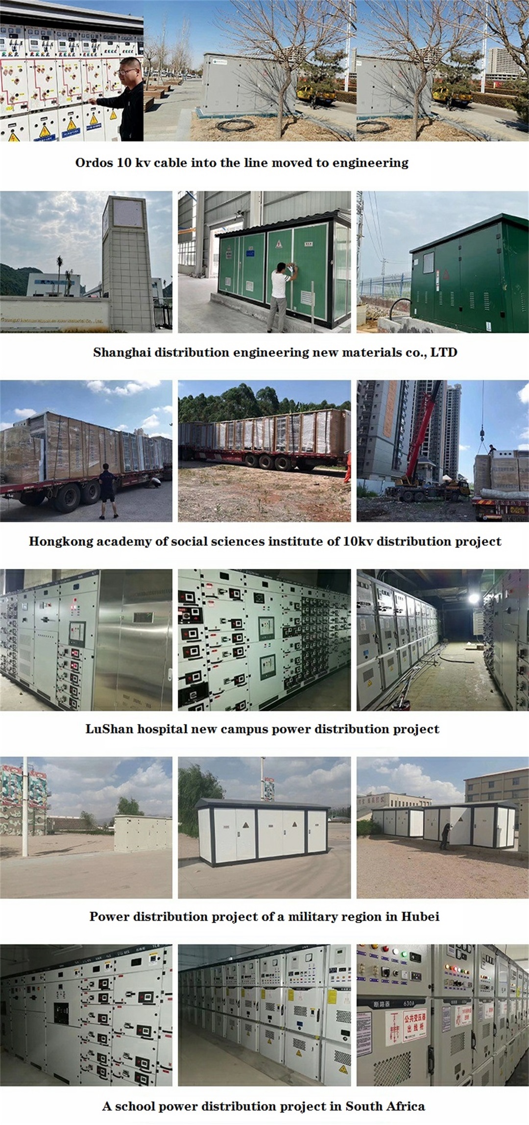
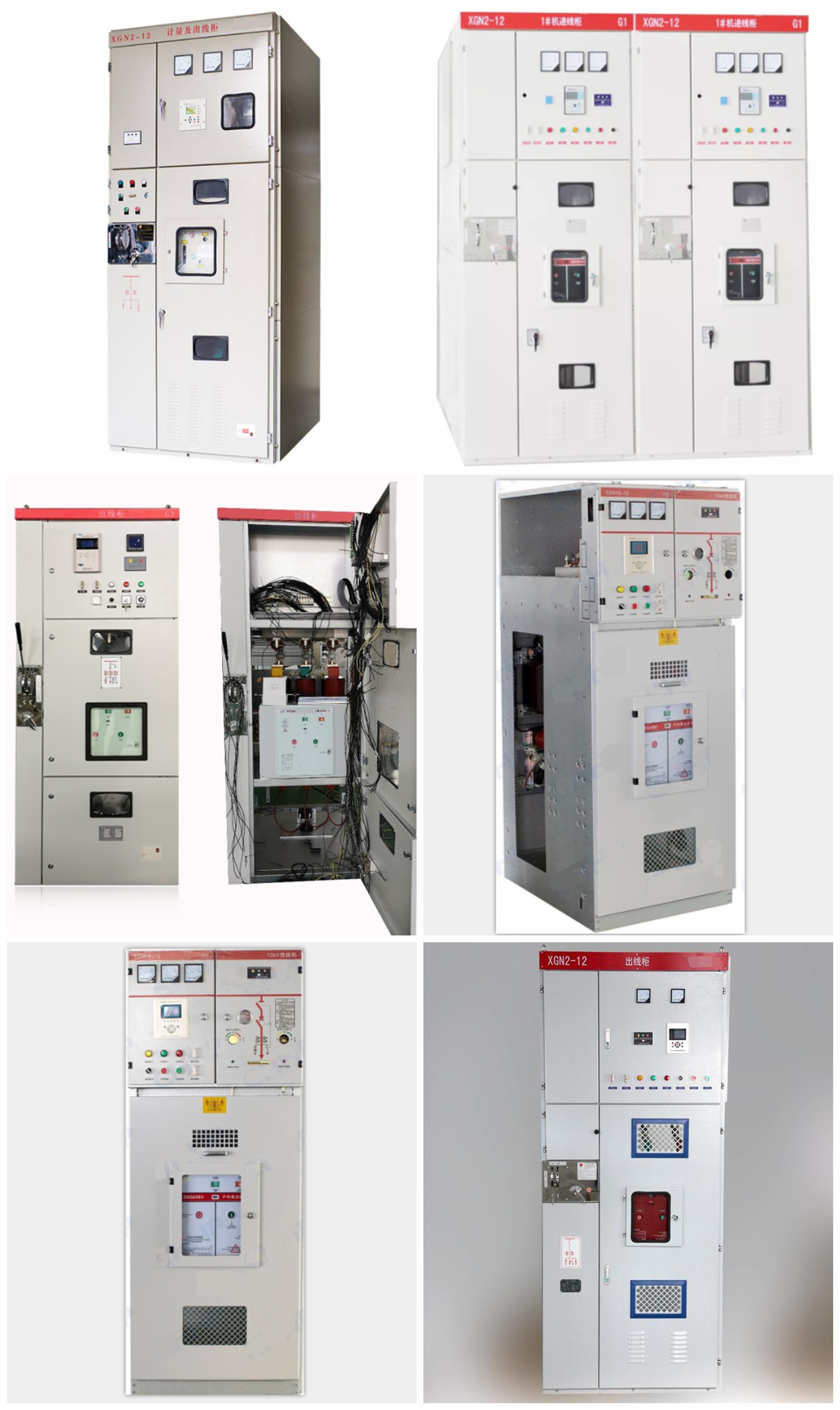
Product details

Products real shot
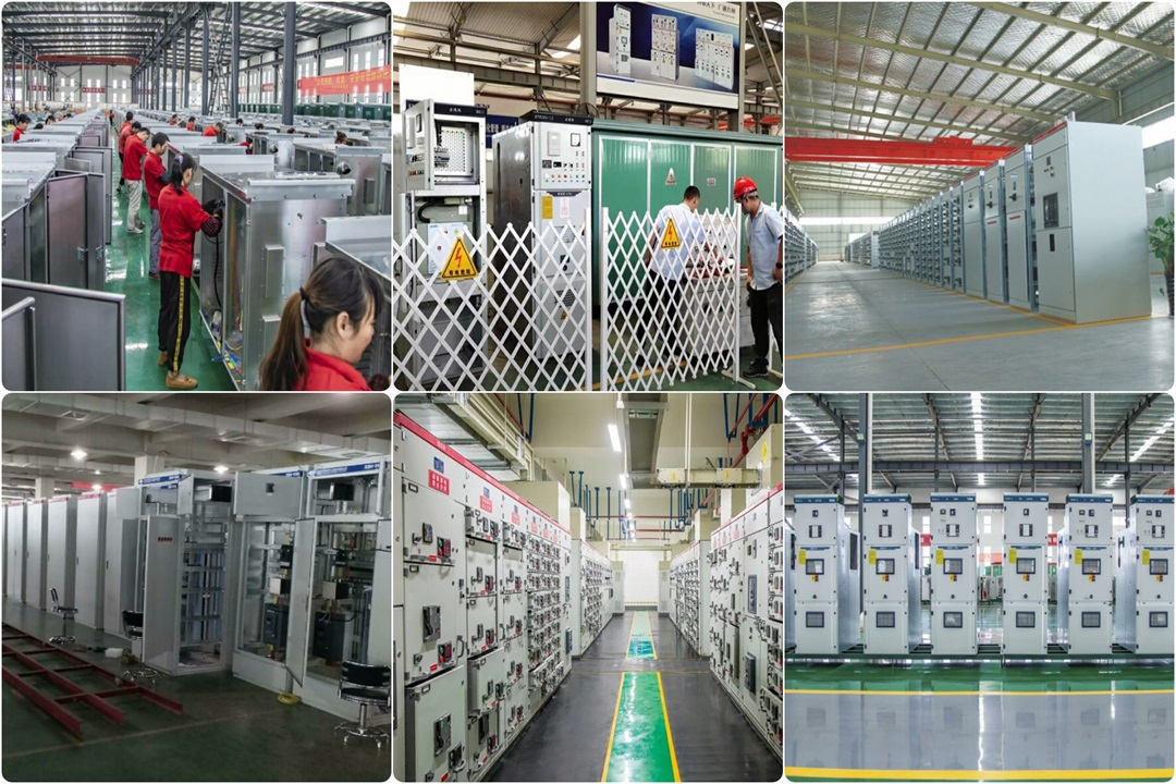
A corner of the production workshop
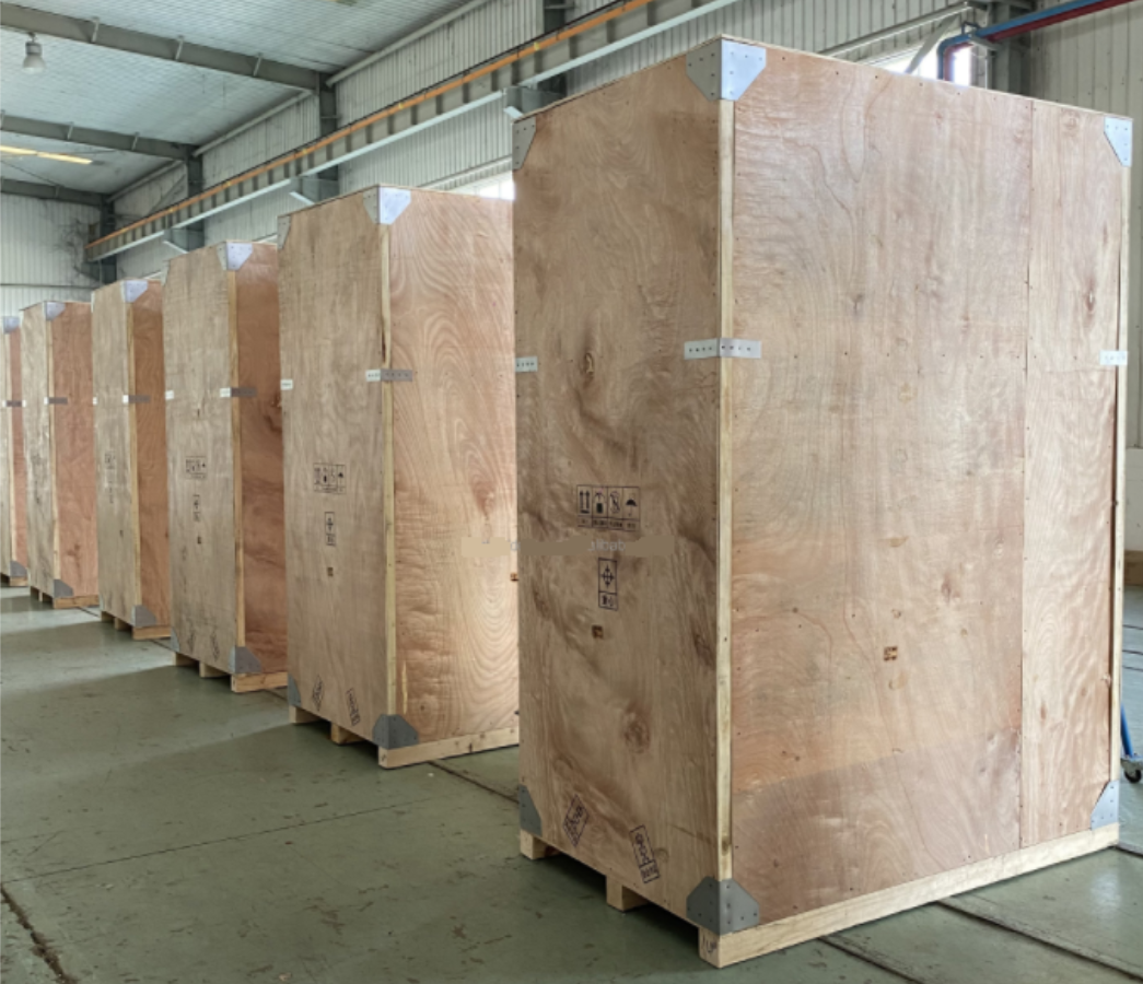
Product packaging
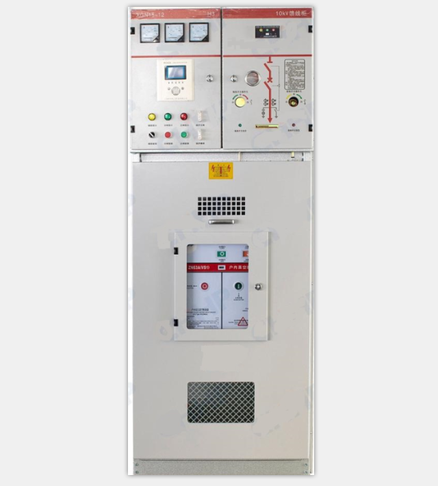
Product application case